Normals, Matrices and Euler Angles
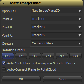 Fusion can import point clouds from a 3D camera track, but there’s no easy way to align an image plane to three points in space. If you want to place walls or floors for camera projection setups, this makes for a tedious task of tweaking angles and offsets. So, I’ve been dusting off my math skills, especially transformation matrices, to write a script that allows you to place an ImagePlane3D or Shape3D with just a few clicks.
It’s a tool script that goes into your Scripts:Tool folder. You need to select a PointCloud3D before running it. Unfortunately, there’s no way for the script to know which points of the point cloud you have already selected 🙁 You need to hover your mouse over the point cloud vertices after you have launched the script to read their names and select the desired points from a list. The script will, however, remember your choices so you can play around with various trackers quickly and you can choose to apply the transformation to existing planes instead of creating new ones. Here’s a video of the process:
Here’s a script to freeze cameras for projection setups easily.
In case you’re curious: these are the steps that are necessary to solve this problem. Maybe it’s useful to somebody solving the same problem.
- A plane is defined by three points, which we have, but Fusion needs a center offset and three Euler angles move an object in 3D space.
- The center can be chosen almost arbitrarily: any point that lies on the plane is fine. For my script, the user is able to choose between one of the three vertices or their average (which is the triangle’s center of mass). The rotation angles can be deducted from the plane’s normal vector.
- To get the normal vector, build two vectors between the plane’s three vertices and calculate the cross product. This will result in a vector that is perpendicular to the two vectors and thus perpendicular to the whole plane.
- This vector alone won’t give you the required rotation angles just yet. You need a rotation matrix first. According to this very helpful answer on stackoverflow, a rotation matrix is created by three linearly independent vectors. These are basically the three perpendicular axis vectors of a coordinate system that has been rotated. One of them is the normal vector (which is used as the rotated Z axis). The second one could be one of the vectors we used to calculate the normal vector. However, there’s an algorithm that can produce a better second vector, one that is aligned to the world’s XYZ axes as closely as possible. This is useful since the plane we’re creating is a 3D object with limited extends instead of an infinitely large plane.
- The third vector we need can again be calculated using the cross product between the normal vector and the result of the previous step.
- To decompose a rotation matrix into Euler angles, there’s a confusing amount of solutions on the web since there are several conventions: row vectors vs. column vectors, which axis is up and most importantly, what’s the desired rotation order (for example XYZ or ZXY?). Fusion uses row vectors and supports all 6 possible rotation orders, so we’ll go with that. The source code can be found in Matrix4.h of Fusion’s SDK. Moreover, this paper (“Computing Euler angles from a rotation matrix”) explains the process quite well.
VFX Breakdown Effect (Breakdown)
I was pointed to an effects reel for “Wrath of the Titans” by Method Studios (you need to watch it on YouTube due to the usual licensing issues):
The shots look cool, but what was more interesting is the way they did the breakdown of their CG elements. Look at the camera moves at 0:14 or 1:17.
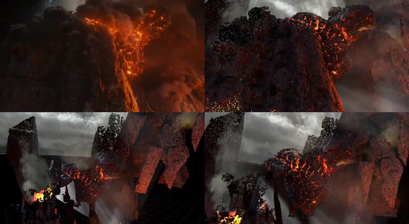
I’ve tried to dissect their technique using a Fusion comp and some random model I’ve downloaded from turbosquid (so don’t tell me it doesn’t look as cool as Kronos in the video above). The way I think this was done was by projecting the rendered passes back onto either real geometry or a recreation of the geometry using a world position pass. The latter is the only feasible solution for scenes with a high polygon count and can also be done as a particle cloud (see the “dissolving” rocks in the stills above).
Then, additional footage is brought in on image planes. Whether the footage was a 2D matte painting to begin with or a CG element doesn’t matter, for the breakdown it’s all treated like a 2D element. You can see this on the flat volumetric godrays.
To spice it up even more, they probably rendered additional passes especially for the breakdown (for example the wireframe pass) using the camera move designed for the breakdown shot. At this point you could also re-render your scene’s FX passes using the new camera move and treat the breakdown shot as if it was an original shot 🙂 Depends on how much work you wanna put into it.
Here’s a quick video that puts all the techniques together: particle cloud, projections, image planes and wireframe pass.
Mosaic Effect in Fusion
I’ve recorded another video tutorial for your viewing pleasure. It’s just a tiny effect, but the video shows that you can take even little tasks like this a bit further.
Rendering rec709 in Fusion
This is part of a series of articles dealing with color workflows in Fusion. Other parts:
Linear Gamma Workflow in Fusion Part 1 and Part 2.
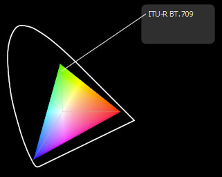
I’ve noticed a couple of Google hits for this topic. Maybe you’re interested in this because Fusion seems to lack a color space selector like Nuke has in its Write node? In Fusion the workflow boils down to using the Gamut tool where rec709 is called by its official name “ITU-BT R.709”. But as with everything in compositing, it makes sense to understand what you’re actually doing since in the end the “how to output rec709” question is just a matter of giving your client what he expects.
The rec709 standard encompasses much more than just the gray-scale gamma curve. It also specifies color primaries, white point and so on which would also affect the hue of your pixels. But usually, if somebody hands you his footage, telling you it’s in “rec709” he probably means that he exported it from his black box editing thingy and he wants the result to look neither brighter nor darker. So I’m mostly dealing with the proper gamma curve for rec709 in this post, not colorimetric mambo-jumbo that I’m still figuring out myself and that mostly concerns DOPs or colorists.
Option 1:
Source footage is a supposed rec709 mov and you’re not using a linear gamma workflow. Fusion won’t do anything to footage it loads in or saves out, so your workflow will simply be this:

Your end result will look the same as your source footage (except for the effect you’ve added). rec709 in, rec709 out. sRGB in, sRGB out. If it doesn’t, then it might be because you’re writing out movs in different codecs and Quicktime does its own unpredictable color shifting. Use file sequences instead. Also, if you’re comparing Fusion’s output to something else in Nuke, make sure both Read nodes are set to the same color space! By default, image sequences are interpreted as sRGB but movs as something else.
Option 2:
Same as before, but you’re working with linear gamma:

The first gamut tool allows you to bring in footage from a different color space as well (sRGB jpegs from a camera come to mind). This is the proper workflow for compositing and also the one used in Nuke.
Note: Fusion 6.4 added a new display-referred rec709 space that is used by ARRI’s Alexa color science. The regular rec709 color space has now been renamed to ITU-R BT.709 (scene).
Option 3:
Linear CGI to rec709. First graph is for a linear workflow, the second one for compositing in rec709 directly. The latter isn’t correct, but useful if you’re afraid of this whole LUT thing…

Option 4:
Source footage is a dpx sequence in a logarithmic format (film or something new like Alexa Log C). Your client wants rec709 for reviews and editing (regardless of what the deliverable will be). You really should be working in a linear gamma workflow here:

To convert from logarithmic to linear you’ll have to set the Loader’s conversion values to those specified by the guy who made the dpx files. If you’ve received Alexa Log C there’s a special conversion that needs to be done. Fusion 6.4 supports it in the Loader and CineonLog tools. In earlier versions you have to bypass Fusion’s log-to-lin conversion that happens in the Loader. Check this forum thread for an implementation of the gamma curve that Nuke is suggesting for Log C or create your own conversion LUTs on ARRI’s site.
The result of the loader will be linear, so a Gamut tool with output space set to ITU-R BT.709 and add gamma enabled results in rec709. Alexa footage will look less saturated than what an editor might see using his ARRI LUT. To fix this, set the Gamut tool’s source color space to Alexa’s wide gamut (requires Fusion 6.4 or later).
Option 4b:
You have also been given a film LUT which the editor would have used to convert logarithmic footage to rec709 on his side. He’s doing more than just a gamma correction so if you’re not doing the same he’ll think you screwed up because saturation and highlights look different. This flow assumes that his LUT expects a logarithmic input which gets converted to rec709:

Don’t use his LUT to convert your footage to rec709 before linearizing it. You’ll lose the dynamic range you could get from the dpx. Better guess some settings for the log2lin conversion in the Loader. As long as you’re using the same values in the CineonLog tool (which goes lin to log), you’re kinda safe.
Update: Ken Turner has more on how to use LUTs in Fusion.
Linear Gamma in Fusion Part 2
In part one, I have written about viewer LUTs to aid my linear gamma workflow. This part provides an example of the complete workflow (without CGI) and talks a bit about the basics. For starters, lots of people have already explained the issue of gamma quite nicely so I’ll make it short, skip the history and relate things to Fusion.
This article is part of a series of articles dealing with color workflows in Fusion. Other parts:
Linear Gamma Workflow Part 1 and Rendering rec709.

How to setup a linear workflow in Fusion (click to enlarge) – update: you can also use the “Select View LUT Plugin” comp script to save your LUT settings
Image Editing is Math
Color corrections, image warping… everything. In math, you rely on basic assumptions, for example that 1 + 1 = 2. A more specific example that relates to VFX is this: if you take two photos with a camera and for the second take you open your shutter twice as long as before, twice the amount of light will be “recorded” and the resulting image will be twice as bright. In other words, every pixel’s value should be twice as much as before. Fusion is using algorithms that expect this to be the case – as does every other image editing and rendering software out there. They expect a pixel that is twice as bright to have twice the RGB values.
So what’s the big deal? Well, the problem is that every image that looks alright inside an image viewer, a webbrowser, Photoshop, Premiere or Fusion doesn’t obey this premise. The files all have their RGB values warped (due to reasons going back to the beginnings of computer graphics and CRT monitors) to look normal to our eyes when viewed on a monitor. But if computer programs are looking at the raw numbers, assuming that twice the RGB means twice the brightness, they are mistaken. Their algorithms result in 1+1 = 3.
Try it yourself. Increase the gain of a photo by a factor of two. All the color values will be twice as high but the image looks very blown out – not like a photo that has been taken with half the shutter speed (or twice the aperture). This is why you’ve been adding one color correction after another, tweaking curves, creating masks for highlight areas and doing all kinds of nasty stuff to an image. You’ve unknowingly been doing math in a universe where 1+1 = 3.
Gamma Correction
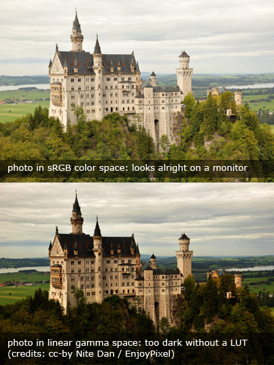 I haven’t used the word gamma yet. In very simple terms, it’s a measurement of how much the color values of an image have been warped and if you read up on it you’ll quickly end up with figures of curved lines, formulas and jargon. Let’s use language a compositor would use (but don’t try to impress your TD, colorist or resident math geek):
An image like the first one to the right that looks good on your monitor by default, i.e. one with warped RGB values, has “gamma”. You need to “remove gamma” or apply a “gamma correction” using a BrightnessContrast or Gamut tool to bring the values back into a dimension where the image is “linear”, i.e. where 1+1=2. Fusion’s algorithms are happy now, your color corrections and defocus effects look much more realistic but oh my… the image is way too dark. But nevertheless, in this dark image, an object that has twice the RGB values really has emitted twice the amount of light towards the camera. Again, this is simplified since digital stills cameras are made to produce visually pleasing jpegs, not physically correct ones.
At the end of your comp, you’ll have to “add gamma” or convert the image back into a “color space” that is suitable for your target audience who will need to see the image with warped RGB values so it appears correctly to human eyes.
Working Linear by Example
The workflow problem that arises is obvious: How do you work on an image if what is being displayed is unnaturally dark? Enter the LUT button. A LUT is a color correction that is applied on-the-fly, just for the viewers, usually in real-time on your GPU. It doesn’t modify the image data of your comp in any way. There are basically two gamma corrections that make sense for a basic linear workflow: sRGB and ITU-R BT.709 (rec709). Both brighten up a linear image for human consumption and differ slightly in perceived brightness (or rather “gamma”).
You should use the same LUT that was used to linearize your footage. If there are no specifications from your grading or editing department, you can’t go wrong with sRGB – although rec709 makes the image appear a bit darker and will prevent you from crushing the blacks too much. But unless you’re working on a calibrated broadcast monitor and know exactly what your editing or grading department and broadcast station does to your images, neither LUT will give you certainty about how it will look to other people. If your task is simply to add something to an otherwise unchanged plate it also doesn’t matter which LUT you’re using as long as you’ve linearized your footage and you’re working in floating point.

Here’s an example comp that demonstrates a feasible linear workflow. It uses a photograph to demonstrate how a defocus produces photorealistic results when applied with linear gamma. It also includes the ViewShaders from my previous post. The next part of this series will discuss CGI and “illegal” operations in linear space.
Linear Gamma Workflow in Fusion
Of course you can work in linear gamma in Fusion. In fact, Fusion expects images to be linear. If you simply load an sRGB image and start working on it, you’re doing it wrong.
This is part of a series of articles dealing with color workflows in Fusion. Other parts:
Linear Gamma Workflow Part 2 and Rendering rec709.

The Problem
Now, it’s been two years since Nuke has set the industry standard for an intuitive linear compositing workflow and Fusion has done nothing to keep up. (update: it’s 2014 so it’s 4 years now and Fusion 7 hasn’t improved the situation…) Why do people still ask in forums if Fusion can work linear or how to set up an sRGB LUT? Because while Fusion’s LUT engine is much more powerful than Nuke’s, its corresponding interface leaves a lot to be desired (to put it politely). While in Nuke you have to consciously do things to break its linear workflow, you have to know what you’re doing to work linear in Fusion. And even then, you’re gonna trip over its LUT GUI all the time. There’s probably a reason why even in eyeon’s official YouTube videos the LUT button is disabled.
The Solution
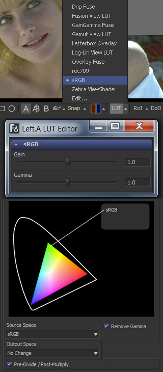 So here’s the deal. You want to view your images in sRGB or rec709 color space, you want to have access to a gamma slider to quickly check your black levels and all of this should be saved in a convenient default for all your comps.
- Download these GPU-accelerated viewshaders: srgb_rec709_viewshaders.zip
- Unzip them into your Fuses directory, usually something like C:\Users\Public\Documents\eyeon\Fusion\Fuses\
- Restart Fusion and click the triangle next to a viewer’s LUT button. Choose sRGB or rec709.
- Enable the LUT by pressing the LUT button.
- Right-click a viewer, then select Settings… -> Save Defaults
Now all you need to do is convert all non-linear images by adding a Gamut tool after the Loader, set its source color space (if unsure, choose sRGB) and make sure the Remove Gamma option is checked (which it should be by default). Done. Oh, the footage should be in float16 or float32 of course. If you’re loading jpegs, make sure the Loader is converting this for you.
You can choose LUT -> Edit… to bring up gain and gamma controls like in Nuke. These settings will be forgotten once you switch to another LUT but they are meant for temporary image checks anyways, so that’s not much of a problem. (update: Fusion 7 or later finally remembers these LUT sliders)
These GUI issues aside, Fusion actually provides an excellent API for writing GPU-accelerated tools. As these viewshaders demonstrate, you can use the CG shader language inside a LUA script (.fuse files). Here are two additional examples that I whipped up in about an hour:
- Alexa LogC to linear or sRGB (play back Alexa footage without converting)
- Letterbox Overlay (preview letterboxing right in the viewer by defining an aspect ratio or the height of the black bars in pixels)
Fusion also allows you to use OpenCL inside LUA which enables you to write custom tools that execute at lightning speed on your graphics card and are compiled on the fly.
A lot of example code comes with Fusion or can be found on vfxpedia. The guys at Anatomical Travelogue have also published the source of some of their plugins and I’m currently putting the finishing touches onto a GPU-accelerated corner pin plugin, the source of which can be found on the pigsfly forum. It took me a couple of days to write, but most of the time wasn’t spent on fiddling with the API or with OpenCL but trying to get accustomed to the matrix math involved.
Appendix
Just to complete this topic, here’s the way you’d set up an sRGB LUT in Fusion without my CG shaders. You need to activate the Gamut View LUT, choose LUT -> Edit and set its output to sRGB and “Add Gamma”. If you switch to another LUT and back to Gamut View, you’ll have to repeat these steps. Bummer. Moreover, this won’t give you a convenient gain/gamma slider like Nuke has.
For this, you would have to activate the GainGamma Fuse first. Then, in the viewer’s context menu go to LUT… -> Add New -> Gamut View LUT. You can now save this combination of shaders as a LUT chain in the context menu’s LUT… section or as a default for the viewport by choosing Settings… -> Save Defaults. You can do the same for rec709 and toggle between both setups using the context menu. The LUT button’s popup menu won’t help you anymore.
Now download those shaders instead and spare yourself the trouble 🙂
Compositing Tutorial Part 2
Here’s part 2 of my compositing tutorial series. It’s still about tweaking the camera move of our turntable shot. This time, I’ll demonstrate some expressions to retime one camera move based on the angle of another one so the projection’s distortion is minimized. You can grab the comps and footage on my tutorial page.
Using these techniques, you can integrate matchmoved footage into modified camera moves. This may be necessary because there were problems with the camera move on set (bumpy, wrong pacing, …), the director changes his mind or the intended camera move wouldn’t have been possible in real life.
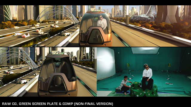
I have employed this technique on the EXPO project. The scene can also be found at the end of the tutorial video. The actor was shot on a turntable and the camera move went like this:
- pull camera away from actor
- rotate actor by 90 degrees
- dolly in
Of course this makes for a really crappy camera move if you add a CG environment since it’ll look nothing like what a real camera crane operator would perform. The final shot was designed in 3D so the plate that was shot had to be integrated somehow. I had to cut out a piece of the original plate, luckily for us the actor was sitting still. After a bit of additional 2D stabilization (the matchmove wasn’t that exact apparently) the plate matched perfectly.
